2018-06-07 share:
The last one:KOYO TRD-S regular shaft encoder replacement factoryThe next one:E6A2-CS3E E6A2-CS3C E6A2-CS5C E6A2-CW3E encoder
What is absolute Encoder and How to use absolute encoder
Measuring system
To solve positioning problems in automation, it is often necessary to measure lengths and angles as exactly as possible. In general there are two different measuring systems:
Incremental Measuring Systems
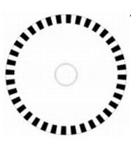
The principle of the incremental measuring system is the scanning of a line pattern on a glass or plastic disc (see Image 1). The states of the line pattern transparent or not transparent are converted into electronic pulses by an opto-electronic unit (e.g. transparent = 5V, not transparent = 0V). The analysis of the signals is performed in an evaluation unit by counting up or down with each pulse. The current count is stored in digital form and is instantly available for evaluation.
However, this method has some serious disadvantages. It is possible that the result is continuously invalid due to signal glitches, unmeasured impulses or similar problems. Furthermore, after a loss of the supply voltage it is often necessary to return to a reference point which can cure complications.
For these reasons applications with a high emphasis on precision or applications where it is complicated or not possible to return to the reference point often use the absolute measuring system.
Absolute Measuring Systems
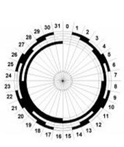
Using this measuring system, every position of the measurement range/angle is identified by a definite code on a glass or plastic disc. This code is represented on the disc in the form of light and dark regions within different tracks. This combination relates to an absolute numerical value.
Thus, the position value is always directly available, counters are not necessary.
In addition it is not possible to get continuously invalid values caused by interferences or loss of the supply voltage.
Movements which are done while the system is turned off are immediately measured after the system is powered up.
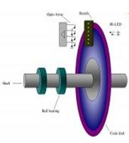
The measuring system consists of a light source, a code disc pivoted in a precision ball bearing and an opto-electronic scanning device (see Image 3).
A LED is used as a light source which shines through the code disc and onto the screen behind.
The tracks on the code disk are evaluated by an opto-array behind the reticle. With every position another combination of slashes in the reticle is covered by the dark spots on the code disk and the light beam on the photo transistor is interrupted. That way the code on the disc is transformed into electronic signals.
Fluctuations in the intensity of the light source are measured by an additional photo transistor and another electronic circuit compensates for these.
After the electronic signals are amplified and converted they are then available for evaluation.
Single-Turn
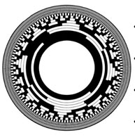
Single turn encoder are encoders that specify the absolute position for one turn of the shaft i.e. for 360°. After one turn the measuring range is completed and starts again from the beginning.
Multi-Turn
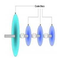
Linear systems normally need more than one turn of a shaft.
A single turn encoder is unsuitable for this type of application because of the additional requirement of the number of turns.
The principle is relatively simple: Several single turn encoders are connected using a reduction gear (see image on left side).
The first stage supplies the resolution per turn, the stages behind supply the number of turns.
The total number of steps in this example is 16 x 16 x 16 x 8192 steps = 33.554.432 steps Binary 111,1111,1111,1111111111111
Angle positions of the shaft are represented by bright and dark spots on the code disk. There are different possibilities to code a position.
Binary Code
The two-state code generates a value from powers to the base of 2. For example the number 10 is illustrated as follows:
1 x 233 + 0 x 222 + 1 x 211 + 0 x 20
The corresponding Binary number is 1010.
The code is a multistep code, i.e. the change from one position to another can cause a shift of several bits. Scanning this code on a code disc would generate a problem, as due to process tolerances changes in the different tracks would not occur simultaneously. As a consequence invalid position values could be given.
Image 6 makes this problem clear: The change from position 7 into position 8 . If bit 23 altered state before bits 20, 21 or 23 then all bits would be dark resulting in an value of 15 being given. The solution is a one step code for example gray-code
Gray-Code
Gray code is a one step code, i.e. only one single bit changes from one position to the next. The transfer from one position can be slightly shifted by imprecise scanning, but it is not possible that this would cause incorrect position values to be given.
Another advantage of the gray code is the easy reversibility. The counting direction can easily be changed by inverting the most significant bit. Therefore it is possible to change the counter direction just by using the complement-entry.
The gray code has to be converted into a binary code, because the single bits of the gray code don’t have a determined value. This is done by a code converter, that consists of a cascaded of XORs.
Transition from 255 to 256 - only 1 bit changes in Gray Code, while 9 bits change in Binary Code
Natural Binary
Grey Code
255
011111111
010000000
256
100000000
11000000
Gray-Excess-Code
The „ordinary“ single step gray code is valid for resolutions which can be described as a power to the base of 2. For other resolutions the range of gray code combinations is limited by concentric trimming. This range doesn’t begin at 0, but is shifted by a determined value.
For evaluation half of the difference between the original and the reduced resolution is subtracted from the calculated binary value.
Resolutions, for example 360° for angle determination, are often realized with this code (Gray code 9 bit cut at both sides by 76 steps equals 360 steps)
All bits of a position are transferred simultaneously using one line for each bit. Data transmission is done by two transistors in push pull circuit. For example the signals can be evaluated via digital entries of an PLC. The conversion from gray to binary code has to take place in the control system, since the code of this method is transmitted directly.
The bit parallel interface is a very fast and for low resolutions cheap possibility of data transmission. For high resolutions or machines of bigger size installation costs can rise rapidly so that other methods of data transmission are more favorable.
For machines where several axis have to be automated (e.g. robots), the cabling of rotary encoders with bit-parallel interface can become a problem, especially when high resolutions are necessary.
A solution for this problem is the synchronous-serial-interface (RS 485/RS 422). The synchronous-serial-interface (SSI) enables a data transmission with only one 6 wire cable.
Drivers that meet the RS 485 standard allow transmission rates up to 10 Mbps/s and line lengths up to 1200 m. This is entirely sufficient for most applications. The maximum transmission rate is dependant on the transmission length.
Only one twisted pair line for the data and one twisted pair line for the clock are necessary. The power supply of the rotary encoders needs only two wires, the same as a bit-parallel interface.
The balanced transmission provides a high noise immunity; crosstalk on the line does not effect the signals.
The twisted pair lines are sufficient for the transmission. But extremely high noise immunity is achieved when shielded twisted pair lines are used.
Transmission
The position value is transmitted synchronously to the clock signal of the control system starting with the most significant bit (MSB).
When non-operational the clock as well as the data line is high.As soon as the clock signal of a clock sequence changes for the first time from low (L) to high (H), the bit-parallel data on the parallel-serial-converter will be stored via an internal SLoad-Signal in the input latch of the shift register. This ensures that the data cannot change during the transmission of a position value. With the following rising edge transition of the clock signal the transmission begins with the most significant bit (MSB).
With each following rising edge transition of the clock signal, the next lower significant bit is set on the output of the data line. After the least significant bit was shifted out, the last rising edge transition of the clock signal switches the data line to low (transmission end).
After the last falling edge of the clock signal, a retriggerable mono-flop determines with its internal delay time tm, how long it will take until the rotary encoder or another encoder can be selected for the next transmission. With this, the minimal admissible break time between two successive clock sequences is determined.
There is a differentiation between single transmission and multi transmission of a position value. To transmit the position value a determined number n of clock impulses has to be placed on the clock entry of the encoder.
For the single transmission this number is n = 13 for the single turn model and n = 25 for the multi turn model.
A multiple transmission of a position value is possible with doubling or multiplying the clock sequence. It is very important that a clock sequence includes n + 1 = 26 clocks for multi turn and n + 1 = 14 clocks for single turn.
After the last Low-to-High transition of a 26-clock sequence, a "L" signal appears on data output. The double (or multiple) successive position values are separated from another with this information.
Since the beginning of the 90’s bus systems are increasingly used, in particular open field bus systems such as Profibus, Interbus and CANbus. Unlike conventional techniques these systems are economically interesting. Field busses are not only economically favorable they also represent a new technology which opens another dimension for the planning of system concepts incorporating dezentralized solutions. Field busses enable the specific communication of automation components – bus nodes – among themselves.
Data exchange
Different bus systems use different principles to transfer data. The most important ones are explained in the following paragraphs:
Master Slave principle with token passing:
The data communication is controlled by the master. Slaves at the bus answer only on request of the masters. Every master has a determined time to exchange data with the slaves. The bus cycle time is therefore calculable. If several masters are available, the bus access right is regulated by exchanging tokens. The master which receives the token, possesses the exclusive right to access the bus.
Priority-controlled data communication:
With this method each user can transmit data at each point in time. To avoid collisions, or to resolve created collisions, there must be mechanisms responsible for arbitration For example, CSMA/CA procedure (carrier sense multiple access with collision avoidance) prevents the emergence of a collision by simultaneous transmitting, the CSMA/CD PROCEDURE (Carrier Sense Multiple Access with Collision Detection) resolves developed collisions.
Shift register with sum framework protocol:
The bus master transmits the output data in each cycle to all slaves and receives as response the input data of all slaves. The small data range of this procedure becomes balanced by a high log efficiency. The bus cycle time is calculable.
Delegated token:
A central bus arbiter regulates the data communication. It distributes the token, according to certain algorithms, to the individual bus users. If a user is in the possession of the token, it can transmit messages. Subsequently, it returns the tokens to the arbiter.
Selection of the bus system
The selection of a bus system depends very strongly on the application. Individual systems are optimized for the main application. Therefore a universal bus system is not possible. The following technical criteria can assist for the selection of a bus system:
- availability of the total system
- test and installation supports
- diagnostic possibilities
- protected data communication
- response time
- availability of the field bus
- components
Encoders are available with all common field bus.
Profibus bus was the first international, open producer-independent standard fieldbus for building, manufacturing and process automation (in accordance with EN 50170). There are three different versions: Profibus FMS, Profibus PA and Profibus DP. Profibus FMS (Fieldbus Message Specification) is appropriate for object-oriented data exchange in the cell and field area. Profibus PA (Process automation) fulfills the request of the process industry and can be used for the intrinsically safe and not intrinsically safe area. The DP version (decentral peripherie) is for fast data exchange in the field of building and manufacturing automation. encoders are ideal for this area.
Structure
A profibus system consists of one or more masters and one or more slaves, which are connected by bus cables and bus plugs. A bus segment consists of a maximum of 32 field devices.
If more devices are necessary, it is possible to link more bus segments by using repeaters (signal amplifiers). At the end of each bus segment a termination resistor must be used. The number of slaves, which can be operated by a master, is dependent on the internal memory structure of the master. Up to 126 stations can be involved in the maximum configuration of a profibus system. The master is usually realized as a connecting module at the control system or as a pc interface card. Typical slave devices are sensors, actuators, transducers or display elements.
The encoder operates as a slave in the profibus system.
Basic principle
Using a software configuration tool, a database is generated which contains the network structure with the necessary configuration and parameter data. The master accesses this database and transmits configuration data to the appropriate users when the profibus system is powered up. After this data is received and stored by the individual users, the system changes to ‘data exchange’ mode. Profibus operates according to the master slave principle with token passing. The master regulates the bus traffic. The request of input data and the writing of output data between the master & slaves are performed cyclically. If several masters exist, the access right is regulated by the exchange of a token.
Characteristics
Transmission technology
RS 485, two-core cable
Baud rate
9.6 kBaud to 12 MBaud
Participants
maximum 32 per segment Expandable to 126 per network with repeaters Mono and multi master systems are possible
Conduit length
1200 m for 9.6 kBaud 200 m for 1.5 MBaud 100 m for 12 Mbaud
Conduit length
independent on the number of participants, transmission rate,lengths of the input/output data.
Encoder with Profibus Interface
The encoder operates on the profibus as a slave. Straightforward configuration is possible by the use of the provided GSD file (electronic data sheet). At the beginning of the configuration the address of the device (which identifies the encoder exactly) and the device class are determined. The selected device class determines the specifications of the encoder.
The professional bus user organization (PNO) describes obligatory encoder profiles, which are called class 1 and class 2. Absolute rotary encoders class 1 cannot be parameterized, rotary encoders class 2 can be parameterized. Additionally rotary encoders have manufacturer-specific additional functions (e.g. velocity output) that can be selected during the device configuration. The selection of the device class also determines the length of the input and output data.
After the selection of the device class is performed, the appropriate parameters (e.g. resolution, direction of rotation, software limit switch, etc..) are saved in a database and transferred to the rotary encoder when starting the system. Data can be read from the rotary encoder (e.g. position value) or written to the encoder (e.g. preset value) using the input and output addresses determined in the configuration. The Baud rate is also determined in the configuration and is detected automatically by rotary encoders. Further adjustments are not necessary with this system.
CAN stands for Controller Area Network and was developed by the company Bosch for applications within the automobile area. In the meantime CAN has become increasingly used for industrial applications. CAN is a multi-masterable system, i.e. all users can access the bus at any time as long as it is free.
CAN doesn’t operate with addresses but with message identifiers. Access to the bus is performed according to the CSMA/CA principle (carrier sense multiple access with collision avoidance), i.e. each user listens if the bus is free, and if so, is allowed to send messages. If two users attempt to access the bus simultaneously, the one with the highest priority (lowest identifier) receives the permission to send. Users with lower priority interrupt their data transfer and will access the bus when it is free again.
Messages can be received by every participant. Controlled by an acceptance filter the participant accepts only messages that are intended for it.
rotary encoders support two CAN protocols: CANopen and DeviceNet.
Characteristics
CANopen
Transmission technology
Two-core cable
Baud rate
20 kBaud up to 1 MBaud
Participants
maximum 127
Cable length
30 m for 1 MBaud5000 m for 20 kBaud
DeviceNet
Transmission technology
Two-core cable
Baud rate
max. 500 kBaud
Participants
maximum 64
Cable length
100 m for 500 kBaud
CANopen
The data communication is done via message telegrams. In general, telegrams can be split in a COB-Identifier and up to 8 following bytes
The COB-Identifier, which determines the priority of the message, is made from the function code and the node number.
The node number is uniquely assigned to each user. With a rotary encoder this number is assigned with by numerical coded turn switches in the connection cap. The function code varies according to the type of message transmitted:
* Administrative messages (LMT, NMT)
* Service data objects (SDOs)
* Process data Objects (PDOs)
* pre-defined messages (synchronization, emergency messages)
PDOs (Process Data Objects) are needed for real time data exchange. Since this messages possess a high priority, the function code and therefore the identifier are low. SDOs (service data objects) are necessary for the bus node configuration (e.g. transfer of device parameters). Because these message telegrams are tranferred acyclicly (usually only while powering up the network), the priority is low.
-Encoder with CANopen-Interface
rotary encoders with CANopen interface support all CANopen functions. The following operating modes can be programmed:
* Polled mode: The position value is only given upon request.
* Cyclic Mode: The position value is written cyclically (interval adjustable) to the bus
* Sync mode: After receiving a sync message by the host, the encoder answers with the current process value. If a node is not required to answer after each sync message, a parameter sync counter can be programmed to skip a certain number of sync messages before answering again.
* Change of state mode: The position value is transferred when changing.
Further functions (direction of rotation, resolution,etc..) can be parameterized. rotary encoders correspond with the class 2 profile for encoder (DSP 406), whereby the characteristics of rotary encoders with CANopen interface are defined. The link to the bus is made by terminal blocks in the connection cap. In additon, the node number and Baud rate are set with turn switches. For configuration and parameterization various software tools are available from different providers. With the help of the provided EDS file (electronic datasheet) simple line-up and programming are possible.
DeviceNet
This CAN protocol is mainly used by Allan Bradley. Due to the protocol structure, the maximum number of users is limited to 64. The maximum data transmission rate is 500 kBaud. Communication is also done by message telegrams (11 bits of identifier and 8 subsequent bytes):
CAN-ID Message Header Message Body 11 BIt 1 Byte 7 ByteThe DeviceNet protocol is based on the system of connections. In order to exchange information with a device, a connection must first be established. The CAN identifier is used for the characterisation of this connection.
-Encoder with DeviceNet-Interface
rotary encoders with DeviceNet interface support all DeviceNet functions The following operation modes can be programmed:
* Polled mode: The position value is only given upon request.
* Cyclic Mode: The position value is written cyclically (interval adjustable) to the bus
* Change of state mode: The position value is transferred when changing.
Additional parameters are also programmable such as direction of rotation, resolution and preset value. The adjustment of the node number and the Baud rate takes place in the connection cap using the turn switches. Easy programming and configuring is possible using the provided EDS file (electronics data sheet) with popular configuration tools.
The INTERBUS was developed by the company Phoenix Contact. The specification has been popular since 1987 and INTERBUS components are available from over 200 manufacturers. INTERBUS is a fast, universal and open sensor/actuator bus system with one master and several slaves. Data transmission rate and expansion of the bus are independent of one and other. The gross data transmission rate is 500kBit/s, the net data transmission rate is 300kBit/s. For special applications with fiber-optic cable data transmission rates of 2Mbit/s are possible. The number of users is limited to 512.
Structure
An INTERBUS system conforms to a ring structure. A compact strand following one direction in the system is used for the bus connection. Beginning at the master (PLC or IPC) the bus system connects the respective control or computer systems to the peripheral input and output modules. The main line of the system is called the remote bus and bridges distances up to 12.8 km between peripheral stations. From the remote bus, branch lines are possible. These branches can be either be an installation remote bus or a local bus.
The data transfer is done using the “shift register with sum framework protocol” (in a data cycle all data is shifted through the ring).
Characteristics
Transmission technology:
• Standard: RS 485, eight core cable because of the ring structure
• Loop: two-core cable, modulated signal on supply voltage
• LWL: fibre optic cables
Baud rates:
• INTERBUS S: up to 500 kBaud
• Loop2: up to 500 kBaud
• INTERBUS LWL: up to 2 MBaud
Participants:
• maximum 512
• Loop: max. 63 per bus clamp
Cable length:
• INTERBUS S: up to 12,8 km (remote bus)
• Loop: max. 200m per loop, 20 m between participants
• INTERBUS LWL: max. 40 m between participants without signal processing
Encoder with INTERBUS-Interface
The absolute rotary encoder is a remote bus user. The individual users are connected by an installation remote bus cable. This cable carries both the bus line coming from the master and the return line. The connection between the rotary encoder and the bus is made by two 9 pin connectors (male and female). An address assignment is not necessary, since the address of the individual users is given by their physical position on the bus. Projecting and parameterization can for example be done with the INTERBUS CMD software or with PC Works.
Encoder profiles
Three profiles are regulated by the user group ENCOM to ensure smooth data transfer between terminals of different manufacturers:
Profile K1: not programmable 16 Bit process data
Profile K2: not programmable 32 Bit process data
Profile K3: programmable 32 Bit process data
rotary encoders can be delivered in K1, K2 and K3.
INTERBUS Loop 2
To connect single sensors and actuators in an economical way, a transmission technology adapted for various common operating conditions was developed.This is called INTERBUS loop. The INTERBUS loop connects terminals to a ring with a simple two-core unshielded cable. Using these two cores data information and voltage supply are delivered simultaneously. The data communication takes place in the form of load independent current signals. By this method the INTERBUS loop becomes so interference-proof that a shielded cable is not necessary.The coupling of the INTERBUS Loop to the INTERBUS remote bus is made by a special bus clamp. 63 INTERBUS loop participants can be connected per bus clamp. The successor of the INTERBUS loop, the INTERBUS loop 2 contains an integrated report and diagnostic manager and enables a larger distance between the users in the loop. The max. distance between the individual terminals is 20 m, the max. loop length 200 m.
INTERBUS LWL
For applications demanding for high noise immunity or high data transmission rates, fiber-optic cables are available as an alternative to the conventional transmitting media. The SUPI 3 OPC (Optical Protocol Chip) is used for these demands. It enables a distance diagnosis and optical power adjustment for LWL transmitters. The fibre optical cable can be easily connected to an existing INTERBUS network with a bus clamp. Advantages of this system are high noise immunity and also data transmission rates of up to 2 MBit/s.
Counting direction
The output value can either increase or decrease when the shaft is turned clockwise (viewed from shaft side).
Resolution/revolution
The parameter resolution is used to program the desired number of steps per revolution. The desired resolution must not exceed the resolution of the hardware.
Total resolution
This parameter is used to program the desired number of measuring units over the total measuring range. This value must not exceed the total physical resolution of the absolute rotary encoder. Revolutions < 4096 are programmable with a combination of the parameters ‘resolution/revolution’ and "total resolution".
Gearing factor
The gearing factor is directly adjustable by the input of desired measuring steps per physical measuring step. With this, very low resolutions (< 1/revolution) can be programmed.
Preset
The preset value is the desired position value, of a particular physical position of the axis. The actual position value is set to the desired position value by this parameter.
Teach-In
A special mode is available for the commissioning phase of the equipment. This makes it possible to change parameters while the encoder is transferring data. For continuous operation another mode is available in which the parameters are protected against unintentional changes.
Velocity
The velocity of the shaft is displayed. Partially the basis for the displaying velocity can be chosen. (e.g. turns/minute).
Software limit switches function:
If the position value exceeds or falls below these limit switches a bit in the output word is set.
Zero point displacement
The zero point is shifted by the entered value. (The setting of the preset value also influences the zero point displacement)
2015 © Shanghai Hengxiang Optical Electronics Co,ltd. all rights copyright Address:Building7,Lane 115,No.1276 Nanle Road,SongJiang,Shanghai,201600 Tel:021-54613487 备案号:沪ICP备12023089号
